
Designing and building a transformer is part science and part art.
Single-phase power transformers are the backbone of electronics. In this section, we will delve into the math of the design process by calculating voltages, currents, turns for each winding, choosing core material, and determining magnet wire sizes.
Part 2:
Designing a Single-Phase Power Transformer
1. Specifications
One of the first steps in the design process is knowing the specifications required. All available information on the transformer being designed must be gathered. For a power transformer, you will need to know the primary input voltage, operational frequency, secondary voltages, and secondary currents. In the US, the frequency of our standard 120V power line is 60Hz. In most of Europe, the frequency is 50 Hz.
The operational frequency can influence the size of the core. The lower the frequency the larger the core needs to be to displace heat and get a lower saturation point. Through practice you will learn what core material and size works the best for the intended application.
If the transformer specification has dimension restrictions, you will have to try to work around the specs the best you can. However, some limitations may simply not be able to be physically met.
2. Voltages and Currents
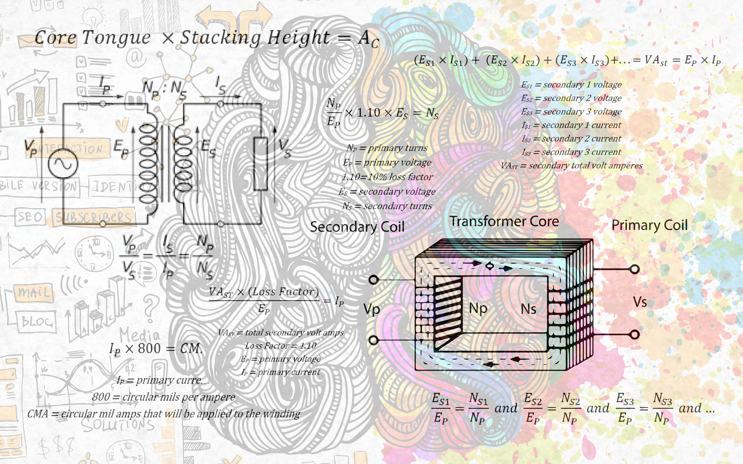
Now you need to calculate your primary currents. This can be done by calculating the VA (volt amperes) of the transformer. The primary VA is equal to the secondary VA. The secondary voltage multiplied by the secondary current gives you the VA of the secondary.


If you have multiple secondaries, the total of the VA’s of the secondaries would still equal the VA of the primary. Multiply the voltage by the current of each secondary, then add the VA‘s of each secondary together to get the total secondary volt amps (VAST).


For calculating the primary current, the following formula may be used.

This calculation is for an ideal transformer, but there are always losses. To mitigate this, we add a loss factor to the equation by multiply the VAST by a loss factor. For a 90% loss factor you could use 1.10.

3. Core Size
Knowing the VA, you can now start to select a core material and size. First, know what type of material you are going to use. There are many different core material types, grades, and thicknesses to choose from. For selecting the best material for your application, consult the core manufacturer’s specifications. The specifications should supply data such as the RMS volt-amps per pound, core loss, inductance, flux density, and other graphs and charts. As you design more power transformers you will get to know what type of cores and sizes best fit the application and/or specifications. There are many books available, like “Magnetic Core Selection for Transformers and Inductors” by McLyman, that are dedicated to choosing a core and magnetism theory, which will give you a deeper understanding on the subject.
The manufacturer should also provide a graph that has the core losses per flux density. This is given in Gauss or kilo-Gauss. For instance, M6 29-gauge steel typically saturates around 18000 Gauss, or 18 kilo-Gauss. We do not want our core to saturate when running at the specifications, so the 18000 Gauss should be considered the upper limiting value. Accordingly, we will choose a core and Gauss for the design that will fit the specification. Again, this will become easier the more transformers you design and build.
Once the core size is chosen, we calculate the area of the core, effective area of the core, and convert the flux density being used to line per square inch for other calculations.

First, calculate the area of the core. For an “E I” core, this is done by multiplying the core tongue by the stacking height.

For the core effect area, multiply the area of the core by the stacking factor.

The stacking factor is the percentage of how full the stack is. Variations in the bobbin and core material do not allow for a 100% stack. The core manufacturer should include a typical stacking factor for their core materials. For example, M6 29-gauge might have an interleave stack factor of 90% (0.90) and a butt stack factor of 95% (0.95). This is dependent upon the gauge of the material and how the core is stacked.
For some of the following calculations we will need to convert the flux density used for our design to lines per square inch. The lines per square inch are calculated by multiplying the flux density by 6.45.

4. Primary Turns
Now, let’s calculate the primary turns for the primary voltage specified. To do this, multiply the primary voltage by 108. The result is then divided it by 4.44 multiplied by the flux density in lines per square inch, multiplied by the effective area of the core, and multiplied by the operational frequency. 4.44 and 108 are constant numbers.

5. Turn Ratio
The turn ratio is the ratio from the primary to the secondary. It is the ratio for voltage, current, impedance, and turns. The secondary voltage divided by the primary voltage is equal to the turns of the secondary divided by the turns of the primary. The turns of the primary divided by the turns of the secondary is equal to the current of the secondary divided by the current of the primary.

For a power transformer with more than one secondary, this would apply to each of the secondaries.

However, these calculations are for an ideal transformer and neglect any losses. Therefore, we add a loss factor in when we calculate the secondary turns.
6. Secondary Turns
Once you know the primary turns, calculate the secondary turns. When calculating this, add the loss factor. This loss factor is to compensate for losses when the transformer is under load. When measuring the secondary voltage unloaded, you will get a higher reading depending on the loss factor. The choice of the core material and flux density design will determine the loss factor (see, the core manufacturer’s specifications). If using a loss factor of 10%, use 1.10 in your calculation. For 5% use 1.05 and so forth.

If there are multiple secondaries, the above formula is used to calculate the number of turns for each secondary winding.
7. Wire Size
Depending on the type of magnet wire material you have selected, you will have to look up the manufacturer’s circular mils per ampere specification for that material of wire. By multiplying the current of the winding by the circular mils per ampere of the wire material, you will you the circular mil amps (CMA) the magnet wire will need for the current of the winding. Looking up the CMA rating of the different magnet wire sizes, choose a wire gauge. For copper magnet wire, 1 amp is about 800 circular mils per ampere.

As an example, let’s say the current calculated for the primary is 1A. This gives you a calculation of 800 CMA. You then look at the manufacturer’s information of magnet wire size specifications. For copper magnet wire, you might choose 21-gauge magnet wire size as it has an 812 CMA rating. Always choose a wire size that is higher than the CMA needed. If current higher than what the wire is rated for is applied, the wire will burn up, causing an “open” in the winding.
Each of the secondary wire sizes is calculated in the same manner. Just replace the primary current with the current of the secondary winding in the formula.
8. Insolation/Wrapper
You will want to insulate between the primary and secondary windings. Depending on the specification design, insulation may also be needed between multiple secondary windings. Again, there are many types of “kraft” paper and tape that can be used. Tape can be a better insulator for the thickness, while “kraft” can give a more even surface for winding. Choosing the right insolation or wrapper is important as it will affect the physical structure of the coil. Not having enough insulation can cause a breakdown of the magnet wire coating, but too much insulation will impact the efficiency and coupling of the transformer. It is best to choose an insulator or wrapper that meets the specifications, including the voltage/current for your design.
When designing a transformer that will be wound on a tube, “kraft” paper will give a better surface for flat layer winding.
Next: Part 3 - Physical Design Calculations
Previous: Part 1: The Basics

2 comments
Hkumar
Hello Sir,
Thank you for Part -2 and Part-3 single phase transformer design steps. I’m wondering for Temperature rise calculation. Would you please provide the Temperature rise calculation ?
That will be really helpful.
Thanks again for your wonderful help.
Hello Sir,
Thank you for Part -2 and Part-3 single phase transformer design steps. I’m wondering for Temperature rise calculation. Would you please provide the Temperature rise calculation ?
That will be really helpful.
Thanks again for your wonderful help.
George Griswold
Great series- thank you.
Great series- thank you.